Modbus Poll Crack + Product Key
Modbus Poll Crack is a Modbus master simulator primarily intended to help developers of Modbus slave devices or others who want to test and simulate the Modbus protocol. With the multi-document interface, you can monitor several Modbus slaves and/or data areas at the same time. For each window, you simply specify the Modbus slave ID, function, address, size, and polling rate. You can read and write registers and coils from any window. If you want to edit a single register, just double-click on the value.
Or you can change multiple registers/coils. Several data formats such as float, double and long are available with word order swapping. Exception errors are displayed in the status line. If you are a slave developer, you can use the “Test Center” to create and submit your Modbus Poll License Key’s own test strings and check the result of the slave in hex numbers. OLE automation for connecting to Excel. To interpret and display Modbus data according to your specific needs. For example, modify the data in Excel, then transfer the data to your slave device!
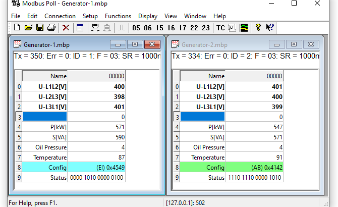
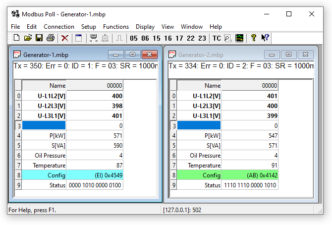
Modbus Poll uses a multi-window user interface. This means you can open multiple windows at the same time displaying different ranges of data or data from different slave IDs. You can write any text in alias cells. In each dialog box, you can press the F1 key to get more help on that specific topic. This image shows two open windows, one reading 10 ID 1 holding registers and one reading 10 ID 2 holding registers. If your slave device allows a holding register to be edited, double-click on the cell or just start typing a new value in the cell.
you may also like this PUSH Video Wallpaper Crack
Modbus Poll Crack Features
- To change the read/write definition of a window, you can press F8 or select Read/Write Definition from the Setup menu.
- Here you specify which data should be displayed in the window.
- This configuration shows how to read 10 holding registers from address 0. Address 40001 in some protocol descriptions.
- Note that Modbus Poll uses Modbus addresses, which always start at 0.
- No data will be displayed if you are not logged in.
- To do this, press F3 or select “Connect” from the connection menu. For more detailed help, press F1.
- This connection uses Modbus Poll Serial Number TCP/IP. There are 5 different connection types available, but only 2 of them are standard Modbus connections.
- The x-axis shows the number of seconds since the start of the graph.
- When the points reach the end of the graph, there are three possibilities.
- Restart at the end: Graph creation restarts from the beginning.
- Continue: it continues until the maximum number of points is reached or Stop is pressed.
- By default, the 4 series are linked to the left Y axis.
- Check the Right Y Axis box if you want to associate a series to the right Y-axis.
Modbus Poll Crack System Requirements
- Click the “Apply” button to apply the changes. Magnifying the chart can be useful if you want to see more detail.
- The zoom is controlled with the left mouse button.
- To zoom in on a specific part of the chart, simply left-click on the chart (this is the upper left corner of the enlarged rectangle) and drag it down to the right. A rectangle will appear.
- As soon as you release the mouse Modbus Poll Keygen button, the axes will automatically adjust to the area you have selected.
- If you left-click on the graph (as if to start a zoom), but instead go to the upper left corner.
- All changes made with the zoom and pan functions will be discarded (the graph will be in the state in which he was).
- Before panning and zooming To move the control, right-click anywhere on the control and move the mouse.
- The point under the mouse follows the movement of the mouse.
Associate data with the chart series - The graph does not know which data to use unless you associate a Modbus data cell with one of the 4 series.
- To do this, select a value cell and select “Link to Chart” under Menu->View.
What’s New Modbus Poll Crack
- MBAXP is a powerful and easy-to-use Modbus ActiveX control that allows Visual Basic.
- Excel, and other OLE container applications to quickly and easily access data from a device.
- Tell the slave which register to start with and how many registers to read.
- The error-checking field provides a method for the slave to validate the integrity of the message content.
- The answer
- If the slave gives a normal response, the function code in the response is an echo of the function code in the request.
- Data bytes contain data collected Modbus Poll Activation Key by the slave, such as B. save values or status.
- When an error occurs, the function code is changed to indicate that the response is an error response, and the data bytes contain a code describing the error.
- The error-checking field allows the master to confirm that the content of the message is valid.
- The controllers can be configured to communicate over standard Modbus networks using one of two transmission modes: ASCII or RTU.
- When controllers are configured to communicate on a Modbus network in American Standard Code for Information.
- In Interchange (ASCII) mode, each eight-bit byte of a message is sent as two ASCII characters.
- The main advantage of this mode is that time gaps of up to one second can occur between characters without an error occurring.
How to Install it?
- When configuring controllers to communicate on a Modbus network in Remote Terminal.
- In unit (RTU) mode, each eight-bit byte required in a message contains two 4-bit hexadecimal characters.
- The main advantage of this mode is that its higher character density allows for better data throughput than ASCII at the same baud rate.
- Each message must be transmitted in a continuous stream.
- In ASCII mode, messages begin with a colon ( : ) (ASCII hexadecimal 3A) and end with.
- A carriage return-line feed Modbus Poll Product key (CRLF) pair (ASCII hexadecimal 0D and 0A).
- Permitted transmitted characters for all other fields are hexadecimal 0…9, A…F.
- Networked devices constantly monitor the network bus for the colon character. When it receives one, each device decodes the next field (the address field) to know if it is the addressed device.
- There may be a gap of up to one second between characters in the message.
- If the distance is greater, the receiving device assumes that an error has occurred.
- A typical message frame is shown below.
Conclusion
In RTU mode, messages begin with a silent interval of at least 3.5 characters. This is most easily implemented as a multiple of the character times at the baud rate used on the network (denoted by T1-T2-T3-T4 in the figure below). The device address is then transmitted as the first field. The allowed characters transmitted for all fields are hexadecimal 0…9, A…F. Networked devices monitor the network bus constantly, even during idle intervals. When the first field (the address field) is received, each device decodes it to know if it is the addressed device. After the last character is transmitted, a similar space of at least 3.5 characters marks the end of the message.
After this interval, a new message can start. The complete telegram must be streamed. If a silence interval greater than 1.5 characters occurs before the end of the frame, the receiving device Modbus Poll Serial Key discards the incomplete message and assumes that the next byte is the address field of a new message. Likewise, if a new message begins more than 3.5 characters after a previous message, the receiving device considers it a continuation of the previous message. This generates an error because the value of the last CRC field is not valid for combined messages.